Procedural Geometry nodes for LightWave
Creating dynamic geometry for animation directly in Layout
Editor
This Mesh Modifier handler allows for creating geometry per frame using nodes. Many operations include names to separate or combine the geometry into named bins of geometry.
Each named bin is a vector containing one or more geometry objects. Each geometry object contains the vertex and polygon data as well as object info such as a transform matrix.
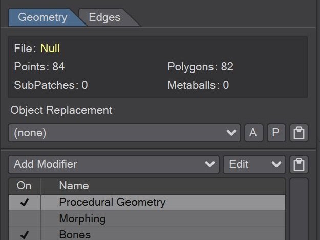
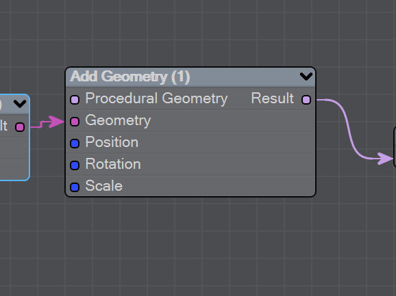
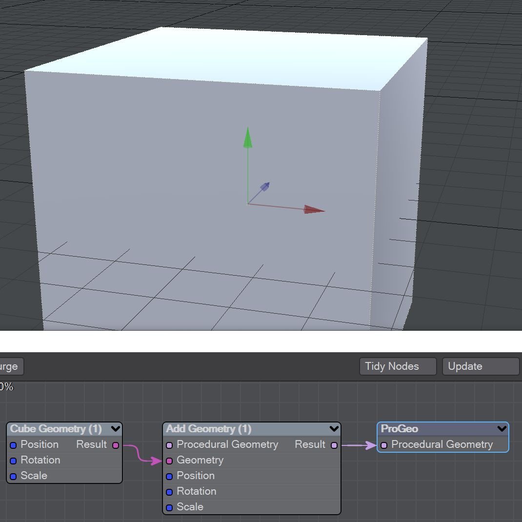
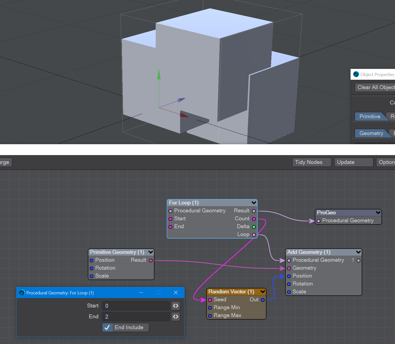
Procedural Geometry is available in the Object Properties window > Primitive tab > Add Modifier menu. When added, three nodes are present by default and a cube will appear in Layout's viewport. On the left - in the Node Editor that appears when you double-click the Procedural Geometry modifier - Primitive Geometry is fed into an Add Geometry node and then the right-most root node: a single input of Procedural Geometry.
Node operations nodal flow
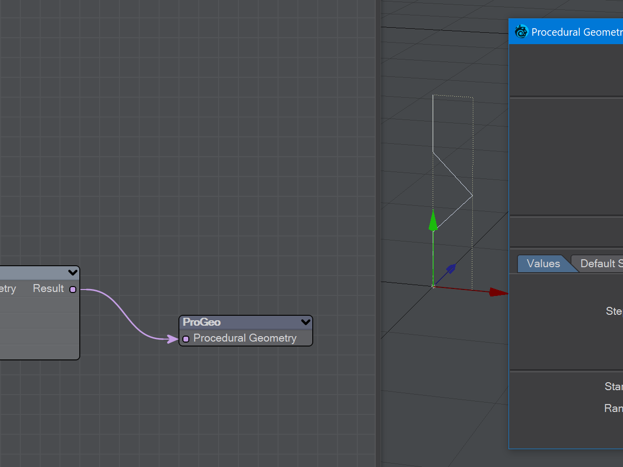
This represents the results of the node operations nodal flow as it is evaluated from right to left.
Nodal flow bin
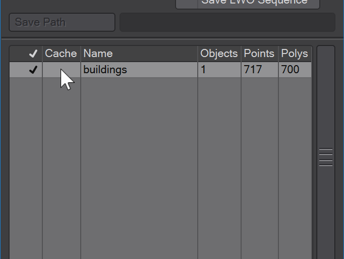
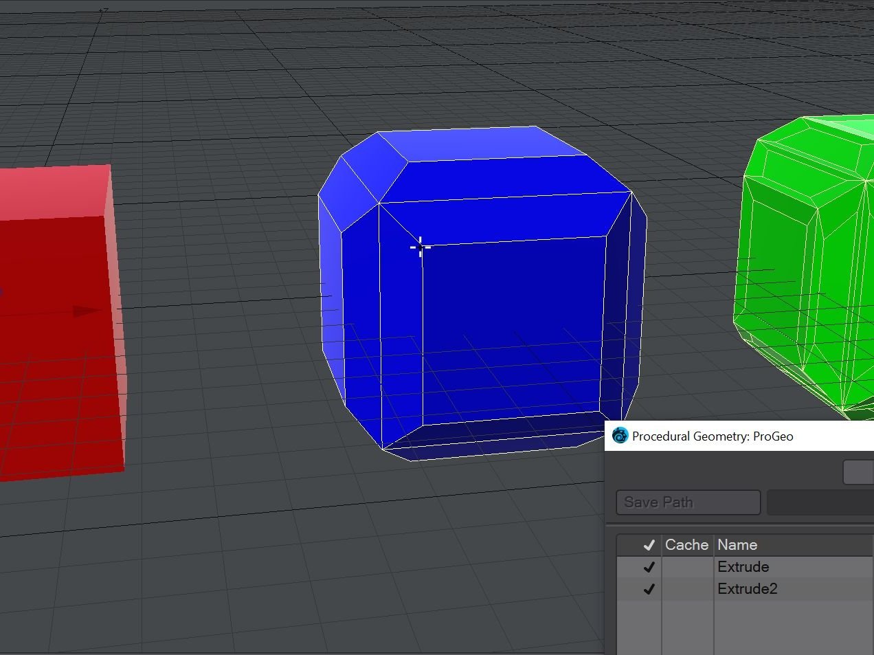
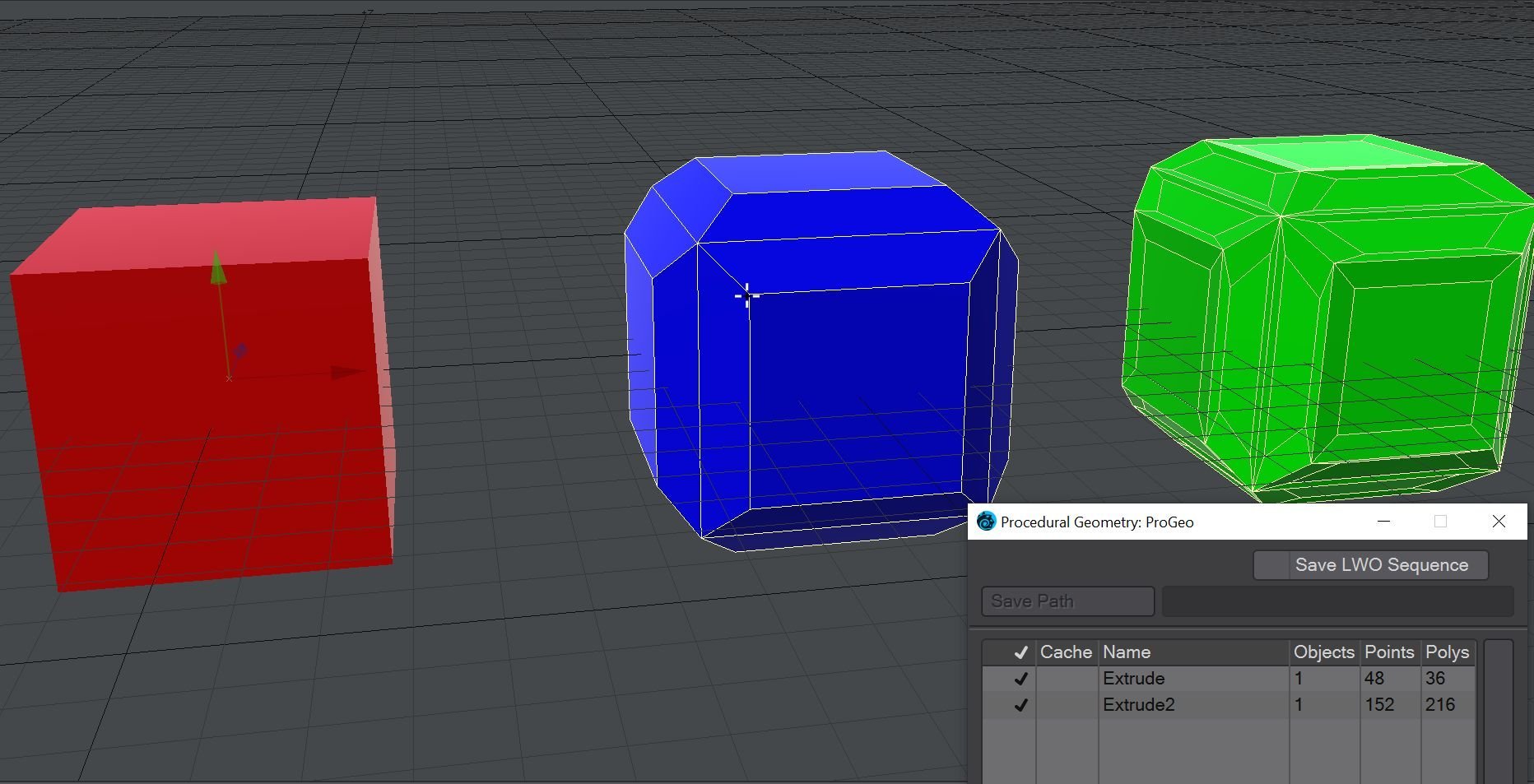
Double-clicking the root node will open a Panel showing the objects in each named bin. Clicking the left check box will enable/disable the polygon creation for that bin. The objects can be cached in memory using the cache checkbox. LWObjects can be saved to disk at each from using the Save LWO Sequence, playing through the frames, and turning it off when finished.
LWO objects can also be saved using the save current object in the save menu.
LWO Objects
Surface names are created for each named object in the bin.
Add Instance
The Add Geometry node is used to add input geometry to the geometry collection.
The Procedural Geometry input is evaluated before the Geometry input is added. Unique indicates that input geometry is added to a different object in the collection and includes a transform matrix.
If a name is not provided here the bin's name will be the same as the input geometry.
Weld will collapse the input geometry into one object and remove duplicate vertices.
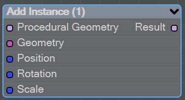
The Add Instance node is used to add input geometry to the Instance collection.
This is intended to be with input scene objects. No geometry is made, It uses the target ItemID from the From Mesh node as the geometry input.
Instancing the ProGeo object itself requires the Instance generator in Object Properties.
Boolean CSG
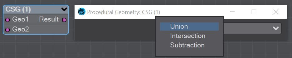
The CSG node is used for creating Constructive Solid Geometry using mesh booleans. This is a non-destructive process. You can choose Union, which unifies geometry; Intersection, which purely shows the overlapping parts of the two objects used; or Subtraction, which takes the second object from the first. Objects need to be solid 3D shapes with no holes.
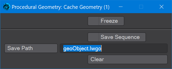
Cache Geometry
You can save Procedural Geometry objects by adding a cache path into the node flow. If an object is particularly complex to make, or going to be rendered across multiple machines, using a cache is a good idea.
The options are:
- Freeze - This will create purely polygonal mesh transforms for saving
- Save Sequence - Clicking this will start saving every change at each frame for this object. Once your scene has been run through, you can disconnect the original nodes and just leave the cache node connected. This will be faster than having to evaluate all the nodes upstream from the cache
- Save Path - The path upon which the .lwgo format cache files will be saved
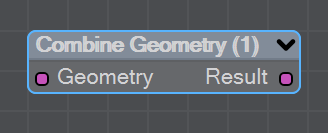
Combine Geometry
This unprepossessing node just has a Geometry input and a Result output. If you double-click the node, you just get a field for naming. As soon as you hook something to the input node, you'll notice you get a new Geometry_1 input. Hook something to that and you'll get another. This node will merely put separate objects into a single one for downstream calculation. There is no Boolean math, they are just stuck together.
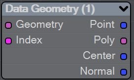
Data Geometry
The Data node is used for getting mesh data such as point locations, polygon counts, center points and normals from a mesh object.
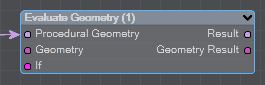
Evaluate Geometry
This node can stop the For Loop operation if the result is not >0 (true).
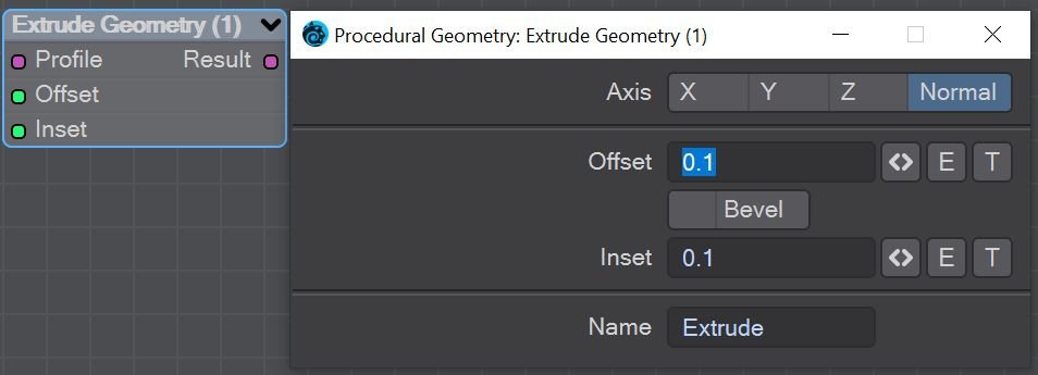
Extrude Geometry
The Extrude node is used for extruding (keeping the original polygon) or beveling (removing the original polygon). Both can have an inset value and be driven by envelopes and textures. If you use the Select Polygons node upstream, you can specify exactly which polygons get extruded.
- Axis - X, Y, Z or the polygon normal
- Offset - Distance to extrude to. Can be animated through the E button and textured with T
- Inset - The distance to bring newly-extruded polygons from the bounds of the original polygon being extruded. Can be animated and textured
- Keep Selection - Checkbox to keep the polygons selected with the Select Polygon node further downstream in node connections
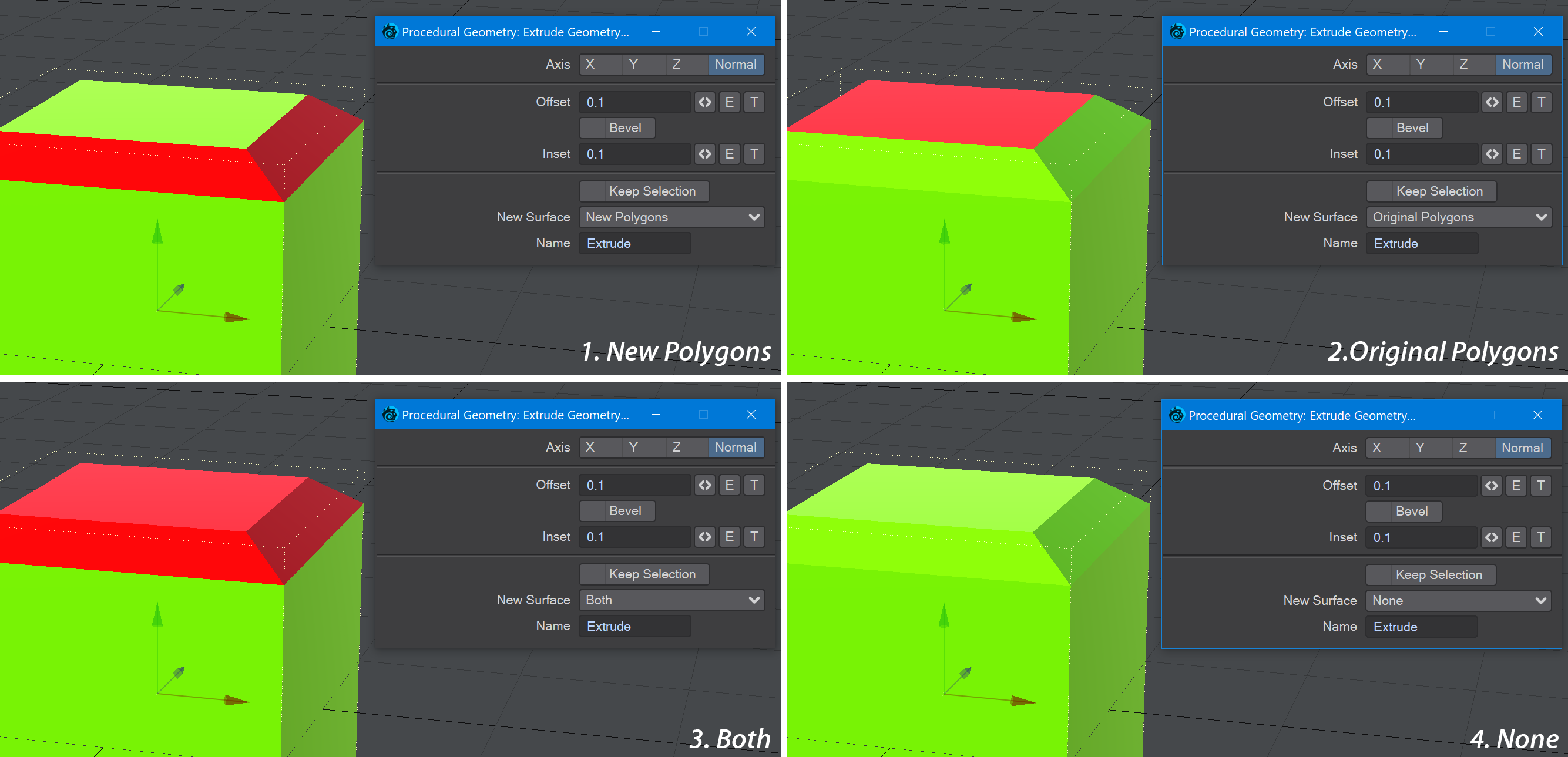
- New Surface - Dropdown with four choices:
- New Polygons - Only polygons created with the extrude will get new surfacing. Essentially, the sides of the extrude
- Original Polygons - Resurfaces the original polygons from which the extrusion was made. Essentially the top of the extrude
- Both - Surfaces original and extruded polygons the same way
- None - Has no impact on surfaces
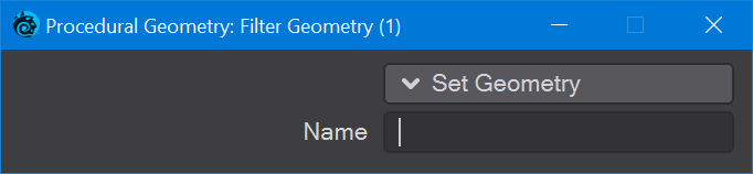
Filter Geometry
The Filter Geometry node is for selecting specific details you wish to use elsewhere. Procedural Geometry goes in and you can choose what comes out. Double-clicking on the node reveals a dropdown menu of network shapes, but there's a text entry in case the item you want is not on the list. The first output, Result, is used with the corresponding Geometry Filter input on the Info Geometry node. The Item Count output outputs the integer count of how many things have been filtered.
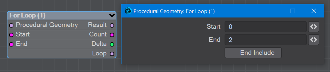
For Loop
The For Loop node is used for repeating an operation between the start and end values.
For Loop can evaluate the input geometry multiple times with the Add Geometry transform position, rotation and scale. The loop can evaluate the Add Geometry and Add Instance nodes.
From Mesh
The From Mesh node will take existing mesh-based objects and use them in a Proceduaral Geometry context. Objects can be transformed or have additional options like MDD point caches or being categorised as Static.
Geometry VDB
This node converts Procedural Geometry objects into VDB objects. The output node for this node requires nodes from the OpenVDB group to continue operations before using the VDB Geometry node to continue as Procedural Geometry geometry.
You can control over Voxel Size (basically the resolution of the object) and Inner and Outer Bandwidths for objects that might not have a consistent amount of detail.
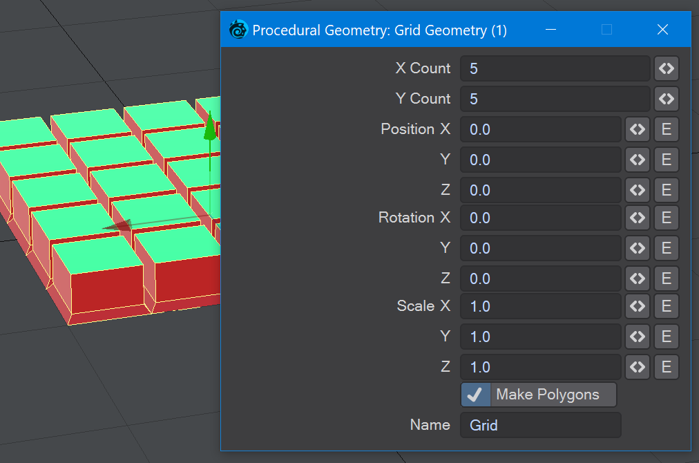
Grid Geometry
Makes a regular grid of x by y cells. You can choose to make the grid visible by using Make Polygons or just have it as a non-rendering base for other objects - instances on the grid points as an example.
Info Geometry
Info geometry
L-System
Introduction
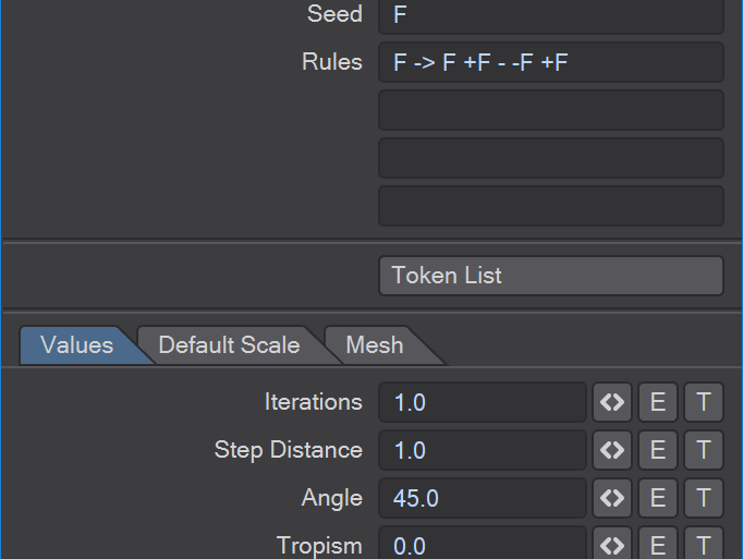
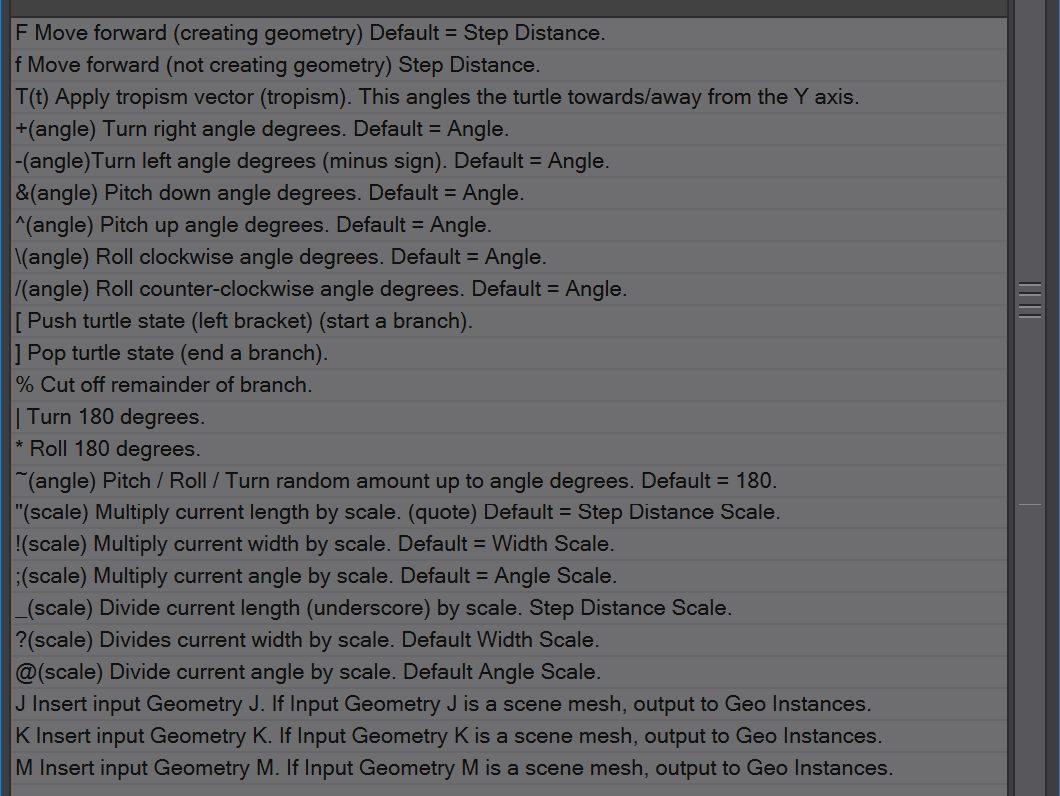
L-systems or Lindenmayer systems - named after Hungarian scientist Aristid Lindenmeyer - are parallel (the four lines of rules are run at the same time) rewriting systems. An L-system consists of an alphabet of symbols called Tokens. There are rules to expand each Token into a larger string of symbols, a Seed string that starts construction, and a mechanism for translating the generated strings into geometric structures that can either be solid geometry or lines shown at render time using edges. If you are familiar with Turtle graphics from school L-Systems should feel similar. With the default when you add the L-Systems node, just try the iterations setting to see how the rules work.
Presets
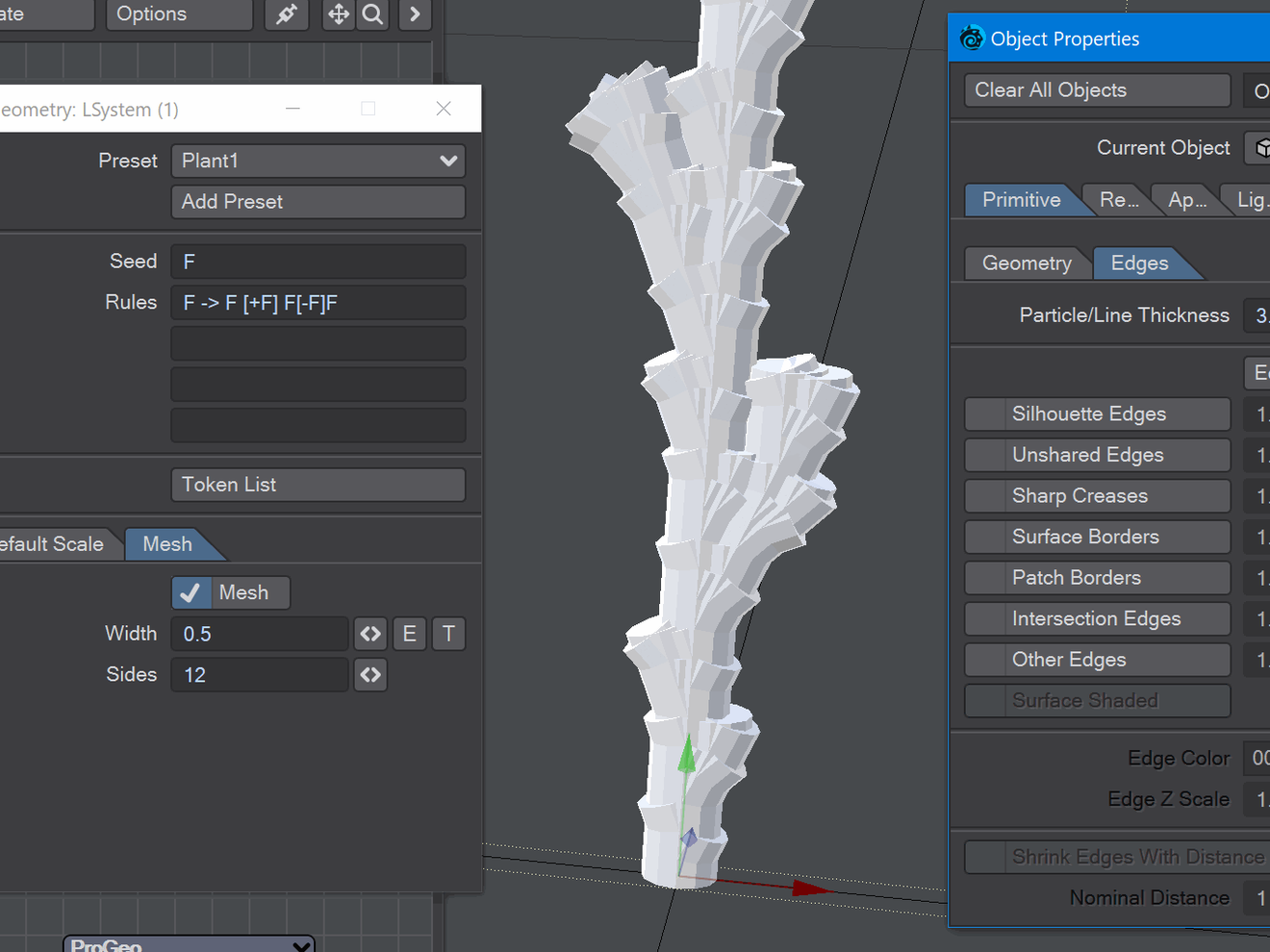
There are several example presets for you to pick apart in the Preset dropdown at the top of the window. There is also a button to add your own. The Seed value is used to start building and four lines of "code" that will be run in parallel to create the L-System. Next is a button to show the complete Token List, which you can refer to while creating your own rules.
Many L-Systems are available online and are easily translatable to LightWave's token format.
Other settings
In the lower half of the window, there are three tabs:
- Values
- Iterations - How many times to repeat the rules
- Step Distance - The default unit of distance travelled for each F
- Angle - The default angle to turn with each +, -, &, ^, \ or /
- Tropism - The default angle T
- Start Direction - This can be Forward, Up or Left and determines the direction of your L-System's travel
- Random Seed - A random number to start your L-System's growth
- Name - The surface name to apply to created geometry
- Default Scale
- These values can all be animated and can change your default Step Distance, Angle and Width over time (the width value is useful for tree growth)
- These values can all be animated and can change your default Step Distance, Angle and Width over time (the width value is useful for tree growth)
- Mesh
- Mesh - A checkbox to decide if you'd like actual geometry created, which can be saved as an object. If you leave this off, you can still render your L-System using Object Properties > Primitive > Edges.
Lerp Vector
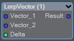
The Lerp node linearly interpolates between vector1 and vector2 by the delta <0,1>.
Line Geometry
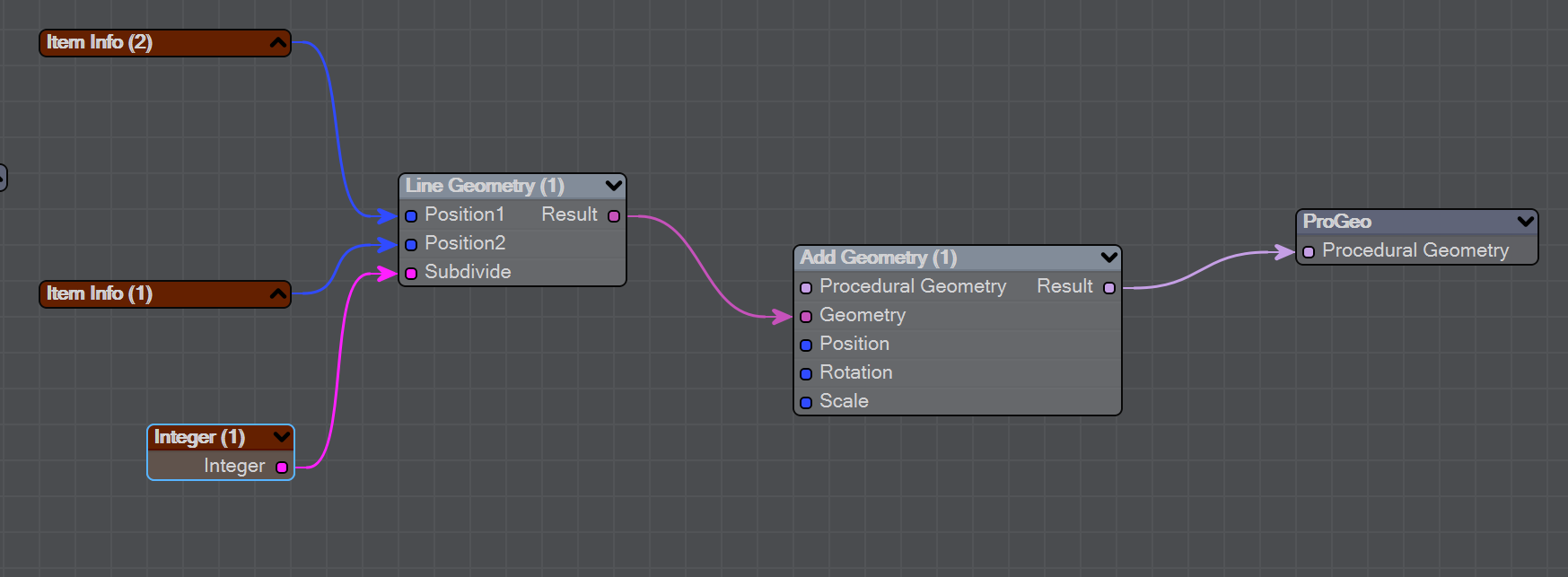
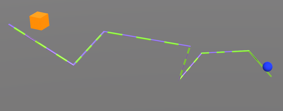
Using three nulls you can create procedural lines in Layout. The first null, call it Nodes, is used for the nodes to create the line, the other two nulls are base and target. Add the Procedural Geometry modifier to the Nodes null and use Item Info nodes with the Line Geometry node to create the procedural line. This line will be rendered using the Object Properties > Edge settings. Remember, a positive number here indicates a line measured in screen pixels (no matter how near or far it is); a negative number indicates a real-world size. The Subdivide Integer input can be used to deform the line using Nodal Displacement in Object Properties.
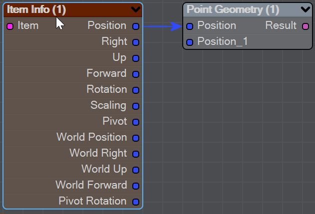
Point Geometry
The Point node outputs points using an expanding list of input points.
When you add an input another input will appear.
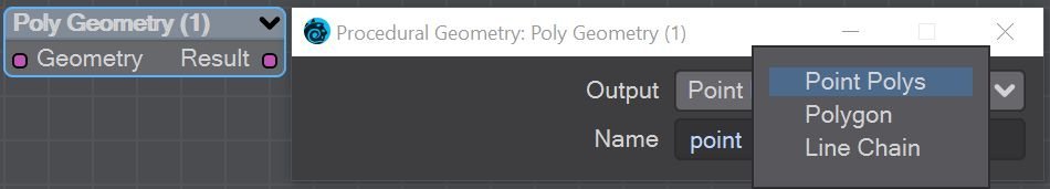
Poly Geometry
The Poly node outputs polygons of several different types. They are as follows:
- Point Polys - Single-point polygons
- Polygon - Outputs a single polygon as x
- Line Chain - Creates a chain of 2-point polys from the first indexed point to the last
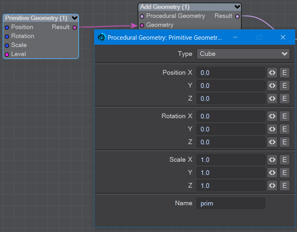
Primitive Geometry
The Primitive node outputs cubes, cylinders or spheres. You can dictate the number of sides for Cylinders or division level for spheres.
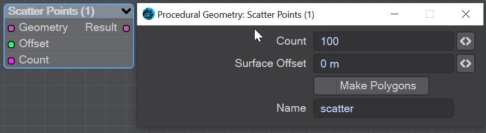
Scatter Points
The Scatter Points node outputs points or single-point polygons offset from the input mesh surface.
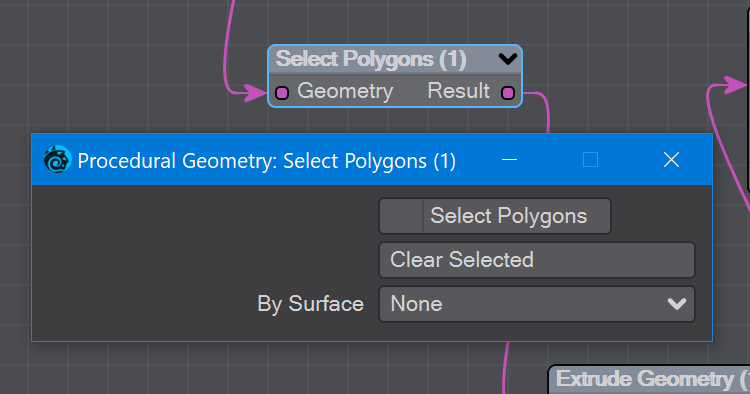
Select Polygons
When you don't want to affect an object completely - just some of its polys - this is the node for you.
Opening the node presents three options:
- Select Polygons - Check this and then select the polygons you want with the LMB. If you want to remove polygons from the selection, use RMB on them.
- Clear selected - Removes the whole selection, essentially deselecting the whole object. In line with the LightWave philosophy, if nothing is selected, everything is selected.
- By Surface - The dropdown represents the object's complete surface list for selection by surface.
Set Position
Set position is used to modify the position of Mesh or Spline geometry in a Procedural Geometry context. The Position Vector input could be supplied by a texture or some other mechanism and the UVBlend scalar input is best fed with a gradient (because they have a built-in UV component).
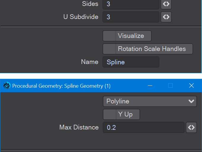
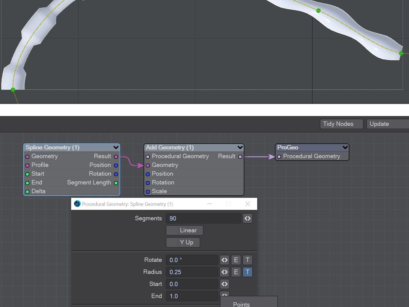
Spline Geometry
Control Overview
When you double-click on the Spline Geometry node, you will be presented with the following options:
- Let's look at Spline-specific controls first. A spline here is a curved line. It has handles at either end to control the tangent. Additional knots can be placed by right-clicking on a knot.
- Y Up - This constrains the spline to having its Y coordinate always in a vertical orientation
- Segments - How many knots are along the whole spline (no matter how many knots)
- Linear - A checkbox to create a spline with sharp corners (the spacing isn't changed, just the tangent interpolation)
- A polyline is a set of straight edges, much as though you are creating this polygonally. Again, additional knots can be placed by right-clicking a knot
- Max Distance - The maximum distance between two knots without a subdivision. You will be able to see them as small bumps on the line or spline
- Rotate - Rotate the items you are using along the spline about the spline. Using Y Up ghosts this option
- The other controls are shared between Spline and Polyline
- Rotate - Rotate the items you are using along the spline about the spline. Using Y Up ghosts this option
- Radius - When using Skin with no other geometry, determines how thick to make the spline
- Start - The visible start for your spline. This can be enveloped or textured
- End - The visible end for your spline. This can be enveloped or textured
- Output - A dropdown with four styles of spline or Polyline to choose from
- Points - Converts the user-created knots and Segments into points
- Skin -The main option and the reason for the radius setting.
- Knots - Uses the user-created knots and automatic tangential knots
- Line Chain - Converts the Polyline into a chain of 2-point polygons
- Sides - How many sides the Spline will consist of when made into polygons
- U Subdivide - Subdivides the length of the spline's automatic UV map
- Visualize - Shows the vectors for each segment of the spline
- Rotation Scale Handles - Add handles to each knot to control that knot's scale and rotation (if you use the Y Up option, Rotation handles will not be shown)
- Name - The surface name and name used for the Procedural Geometry destination node window
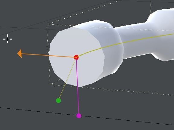
Gizmo
The Spline node features a gizmo with transforms. and an edit menu.
Menu
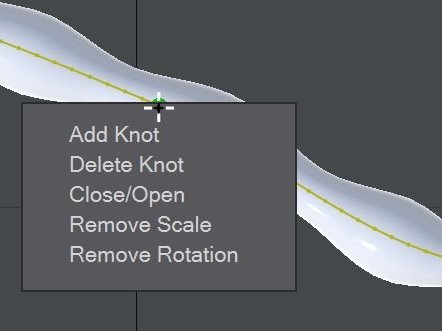
The gizmo has a right click menu.
Rotate and scale
The gizmo has rotation and scaling handles per knot.
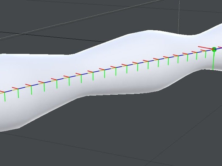
Visualization
The gizmo has a visualization showing the changing transforms at each segment along the path.
Transform Path
The Transform Item node can move an item along a spline path. In this example, the spline path has a multi-polygon profile extrusion.
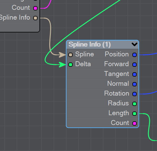
Spline Info
Spline Info
This node is used for downstream access to the Spline Geometry node. The input nodes are Spline, which is always only ever fed by the Spline Info output from the Spline Geometry node and Delta, which is used for the value of the distance from the start of the loop <0,1>. The node will output Position, Forward, Tangent, Normal, Rotation and Radius at the given distance from the start of the spline. Radius is the interpolated radius values along the length. Length refers to the distance between points and Count is the current iteration.
Transform Item
Used to transform (change position, rotation or scale) an item in a Procedural Geometry network.
VDB Geometry
Converts from an OpenVDB SDF to Procedural Geometry geometry. You can give the resulting object a new name if desired.